
· One min read

RATGDO UI

I have created a web app based on React, Material UI and mqtt.js to communicate with RATGDO via MQTT.

It's available to download and run as a Docker container - docker pull ghcr.io/kidproquo/ratgdo-ui:v1.0

Setup

Run the Docker container - docker run -d -p 5175:80 --restart=unless-stopped --name ratgdo-ui ghcr.io/kidproquo/ratgdo-ui:v1.0

info

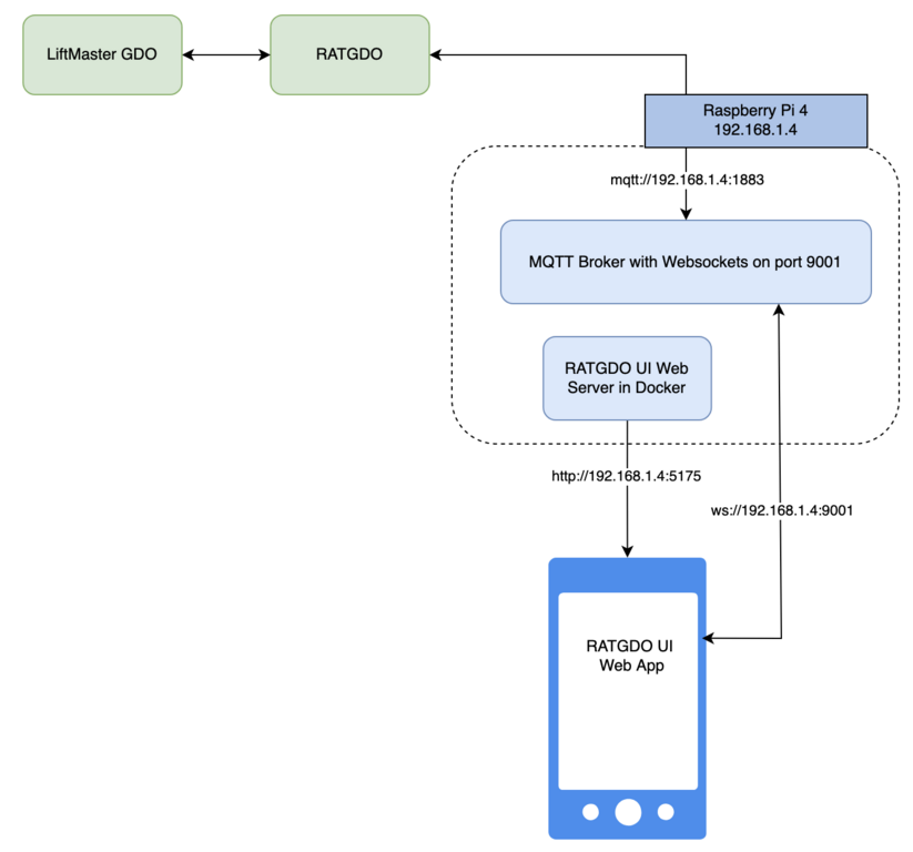
The IP addresses and ports below are only for reference. Those are specific to my setup. Adapt them to suit your setup. I have the docker container's HTTP port mappped to 5175, so the RATGDO UI will be accessible at http://192.168.1.4:5175.

Setup diagram

Requirements

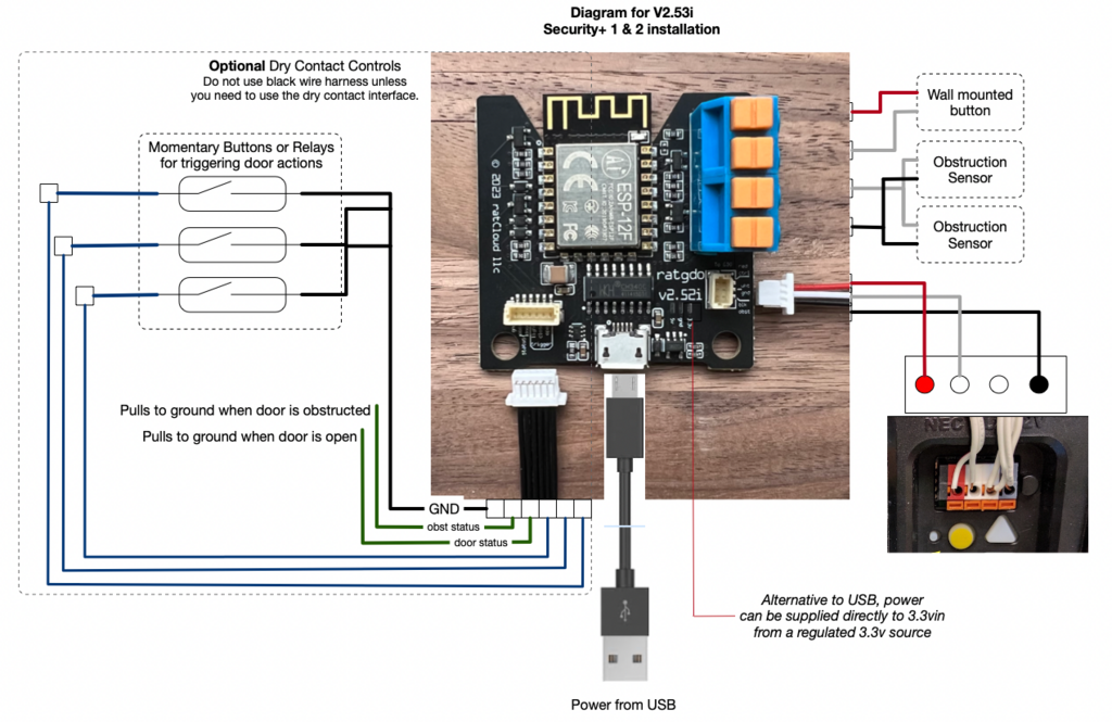
  • RATGDO wired up and running the default MQTT firmware
  • RATGDO configuration set up done (MQTT broker settings, MQTT prefix and RATGDO device name)
  • MQTT broker with websockets enabled

First time access to the UI will show the settings page.

Settings page

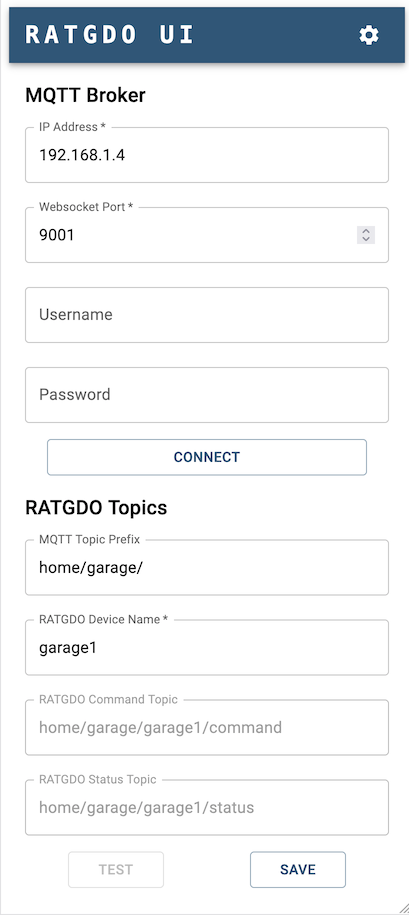
You can test connectivity and communication to the RATGDO using the Connect and Test buttons. Tap Save to store the configuration in the browser's data cache (LocalStorage). Subsequent access of the UI should load the settings from the cache.

tip

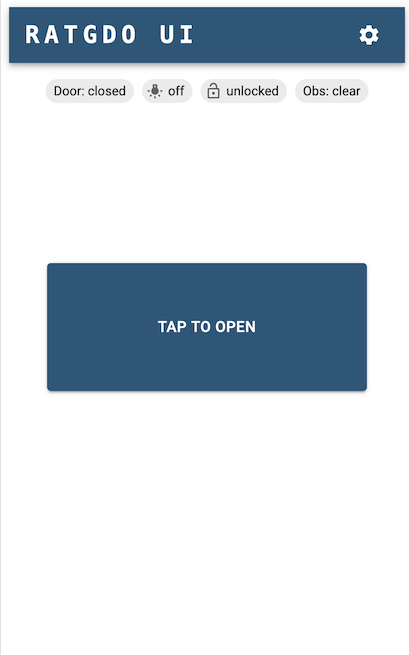
Tap on the RATGDO UI banner to go to the home screen

· One min read

I ordered the v2.5 version of the RATGDO board.

The wiring instructions refer to the newer yellow button version of the LiftMaster Garage Door Opener (GDO).

v2.5 wiring

I have a LiftMaster GDO with the purple button.

Liftmaster GDO Purple Button

Steps

  1. Disconnect the wall mounted button leads from the screw terminals on the GDO, labelled 1 and 2. Connect them to the RATGDO passthrough terminals labelled "Wall mounted button" in the wiring diagram.
  2. Disconnect the obstruction sensor leads from the screw terminals on the GDO, labelled 2 and 3. Connect them to the RATGDO passthrough terminals labelled "Obstruction Sensor" in the wiring diagram. Note: you will be twisting the White/Gray ground leads together into a single terminal slot, and the Red leads together into another terminal slot.RATGDO
  3. Connect the RATGDO colored leads into the screw terminals on the GDO. RATGDO leads connected
tip

You can skip the first two steps. The passthrough terminals are for convenience so that you don't have too many wires bunched up on the GDO terminals. You can have the RATGDO colored leads simply added to the existing connections on the GDO screw terminals.

· One min read

USCIS publishes a "visa bulletin" every month. This bulletin summarizes the availability of immigrant numbers during each month for: "Final Action Dates" (FAD) and "Dates for Filing Applications" (DOF) indicating when immigrant visa applicants should be notified to assemble and submit required documentation to the National Visa Center.

Here's a sample taken from the February, 2023 bulletin:

Sample taken from the April 2023 bulletin

Python Pandas can read html and extract tables into DataFrame objects. This was used to convert each table in the visa bulletin into DataFrames for the family and employment-based dates. This was done for every bulletin published from January 2018.

There are few entries with non-dates. Such as C for current and U for unavailable. C entries were replaced with the 1st of the month. For example, the FAD for INDIA and F2A in the above sample would be updated to 01FEB23. U entries were replaced with 01Jan1980.

Data

Month
ROW
INDIA
CHINA
MEXICO
PHILIPPINES
Jan 2018
2018-01-01
2018-01-01
2018-01-01
2018-01-01
2018-01-01
Feb 2018
2018-02-01
2018-02-01
2018-02-01
2018-02-01
2018-02-01
Mar 2018
2018-03-01
2018-03-01
2018-03-01
2018-03-01
2018-03-01
Apr 2018
2018-04-01
2012-01-01
2012-01-01
2012-01-01
2012-01-01
May 2018
2018-05-01
2012-01-01
2012-01-01
2012-01-01
2012-01-01
Jun 2018
2018-06-01
2012-01-01
2012-01-01
2012-01-01
2012-01-01
Jul 2018
2018-07-01
2012-01-01
2012-01-01
2012-01-01
2012-01-01
Aug 2018
2016-05-01
2012-01-01
2012-01-01
2012-01-01
2012-01-01
Sep 2018
2016-06-01
2012-01-01
2012-01-01
2012-01-01
2012-01-01
Oct 2018
2017-04-01
2016-06-01
2016-06-01
2016-06-01
2016-06-01

Charts

Last Update: April 2023

Jul 2018Mar 2019Nov 2019Jul 2020Mar 2021Nov 2021Jul 2022Apr 202320052010201520202025

· 2 min read

Requirements for RiffPod:

  1. Receive UDP packets from the device, convert them audio samples and save them as WAV files
  2. Playback, manage and share the saved recordings
  3. Show connectivity status
  4. Show audio signal strength

Original design spec:

Simulator

I created a Python script that generates a sinusoidal audio wave, converts it to UDP packets using the same format as the RiffPod hardware and streams to the app. This made it much easier to test, without needing the hardware.

Video showing the simulator in action with the first version of the Unity-based app:

App Architecture

A background thread binds to a UDP socket, listening for audio data from the device/Python simulator. Data is saved to an audio buffer in memory.

The audio buffer length is 10 minutes. This means a single recording is limited to a maximum of 10 minutes in length. TO-DO: Remove this limitation by introducing a circular buffer and another consumer thread that would write the data to disk.

Everything else happens on the main UI thread, leveraging Unity's Start and Update callbacks and input event handling. User taps the Record button, record timer starts ticking, data gets stored in the audio buffer. User taps the Stop button, gets prompted for the recording file name, data gets saved as WAV files in the app's persistent data folder. RiffPod is a 2-channel device i.e. it supports streaming audio from two instruments; for e.g. a guitar and a microphone. Three WAV files get created for every recording - the microphone audio, the guitar audio and stereo file with both microphone and guitar.

App UI

I tried to cram everything together into a single screen, which forced a landscape layout. This required the user to user both hands, which was awkward when you had a guitar and/or mic to manage as well.

Switched to portrait, with separate screens for recording and file management.